BIM works flows of using Autodesk products, such as Infraworks, Civil 3d, Map 3d, Recap Pro and Navisworks that makes my life easier.

Showing posts with label Map 3d. Show all posts

Tuesday, January 26, 2016

GIS into Revit using Dynamo

Revit does not have a import function for a GIS ESRI Shapefile. There are multiple work follows of using MAP 3d or Civil 3d and then importing a .dwg into Revit. Dynamo and the package of GIS  now allows the import function of points, curves and Polygons. The current Package on Dynamo only imports the geometry with in the Shape file and not attributed information, this is currently not available with in the GIS package.


The image of the Dynamo script below uses GIS package in Dynamo to read the shape file and insert point families into Revit. As noted before only the point and curve geometry is import into Revit, no attributed data. The Points are matrix transposes the point to suit the Revit base point to insert point base family in the correct location.


The above appears to be complex set of node but real are just a simple connection of node that performs a simple task; 

1. Read the ESRI Shapefile
2. Process the ESRI Shapefile into list
3. Get the Project Base Point and rotation
4. Matrix transform the point form the Project base point
5. Insert Point family from the transformed base points


The above image is a group of nodes to read the ESRI Shapefile

The process in the above image includes to read the entries of the points with in the Shape file. The result of the list on points is need to be inserted into the Code block to list


Group of nodes to get the project base Point.


The next node group is thanks to Wikipedia! If you can under stand Revit shared coordinates well try think of it backwards!!!

Revit's project base point is the mathematical set out point of the graphical data base. The project base point removes large numbers from the data base and makes the math simple. I actually don't know how to write it in words but to put it simple if you had the option of x =235982030, y=230923092, Z=14000 vs  x=1, y =1, z = 1 for every point as a reference point which one would you chose?  Well Revit makes it simple by using 1,1,1 and tell base point is the large number which is multiplied by linear algebra.  To get the reverse into Revit from Dynamo you need to take the points that you have and Matrix transform them from the Project base point and rotation to true north. Year 12 linear algebra, comes to mind.

Refer to the Wikipedia for Matrix transform https://en.wikipedia.org/wiki/Transformation_matrix

Rotation[edit]

For rotation by an angle θ clockwise about the origin the functional form is x' = x \cos \theta + y \sin \theta and y' =  -x \sin \theta + y \cos \theta. Written in matrix form, this becomes:[4]

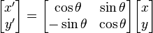
\begin{bmatrix} x' \\ y' \end{bmatrix} = \begin{bmatrix} \cos \theta &  \sin\theta \\ -\sin \theta & \cos \theta \end{bmatrix} \begin{bmatrix} x \\ y \end{bmatrix}

Simple math but complex to get at the start. 

Once the Points have been reversed transform then can been used as points with in Revit


Download the updated dynamo script Link
Download the shape file Example Link


Wednesday, June 10, 2015

Copying Coordinates System

A couple of years ago I wrote about how to create a local grid system for Perth coast Grid PCG94. You can copy the user definition of grid system from PC to PC using the following workflow, which Civil 3d, Map 3d and Infraworks access to the copied grid system.
The PC that does not have the defined Local grid system will need to configure Civil 3d or Map 3d to allows a definition of the grid system to be copied from PC to PC. The copied coordinates system will now be available in Infraworks. 
  • Set your workspace to Planning and Analysis
  • On the Map Setup Tab - Coordinate System click on the options (Small little arrow in bottom right-hand corner)
Coordanites System

The AutoCAD Map 3d option dialogue box and find the Coordinates system tab.

Automatically Add Defination to Dicatonies

Coordinate System Definitions Stored in Drawings select Prompt User or Automatically add.

Now open a .dwg that contains the user-defined coordinate system from the other PC that has the defined coordinate system. The defined coordinate system will now be available on the PC that previously missing the user-defined coordinate system including
Infraworks.
pcg94 define
You can download a sample .dwg that contains Perth Costal grid here PCG94