I walk to work every day from the train station to the office. I thought I'd share my journey, with the entire route which has been captured by point cloud and all the in ground services modelled.
The 1.5 km Journey does not take me 2:30 minutes
https://www.youtube.com/watch?v=AqFlpCZFphw
The point cloud data equated to 3 GB per 100 meters. The point cloud data was processed with Recap Pro and service modelled in Autodesk Civil 3d. Both data sets were overlaid in Autodesk Navisworks and the viewport transition to create the animation.
So how did I manage to Create a render animation with 3 GB x 15 = 45GB.
The workflow to create an animation with s large point cloud data set
- Create and save the first viewport. The viewport needs to have the correct target eye level.
- Apply a section box to the view, while keeping in mind the view depth to be limited. The intent of the section is to limit the amount of point per view when rendering the animation.
- Update the viewport. Edit the viewport setting.
- Pan forwards 100m or so to the desired location. Save the viewport and drag the section boxes.
- Keep creating and staging the viewports, until the final desired location.
- Now to stitch all the views together, create animation folder and drag in your views.
- Click play and watch your animation.


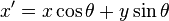 and
and  . Written in matrix form, this becomes:
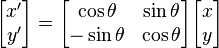


